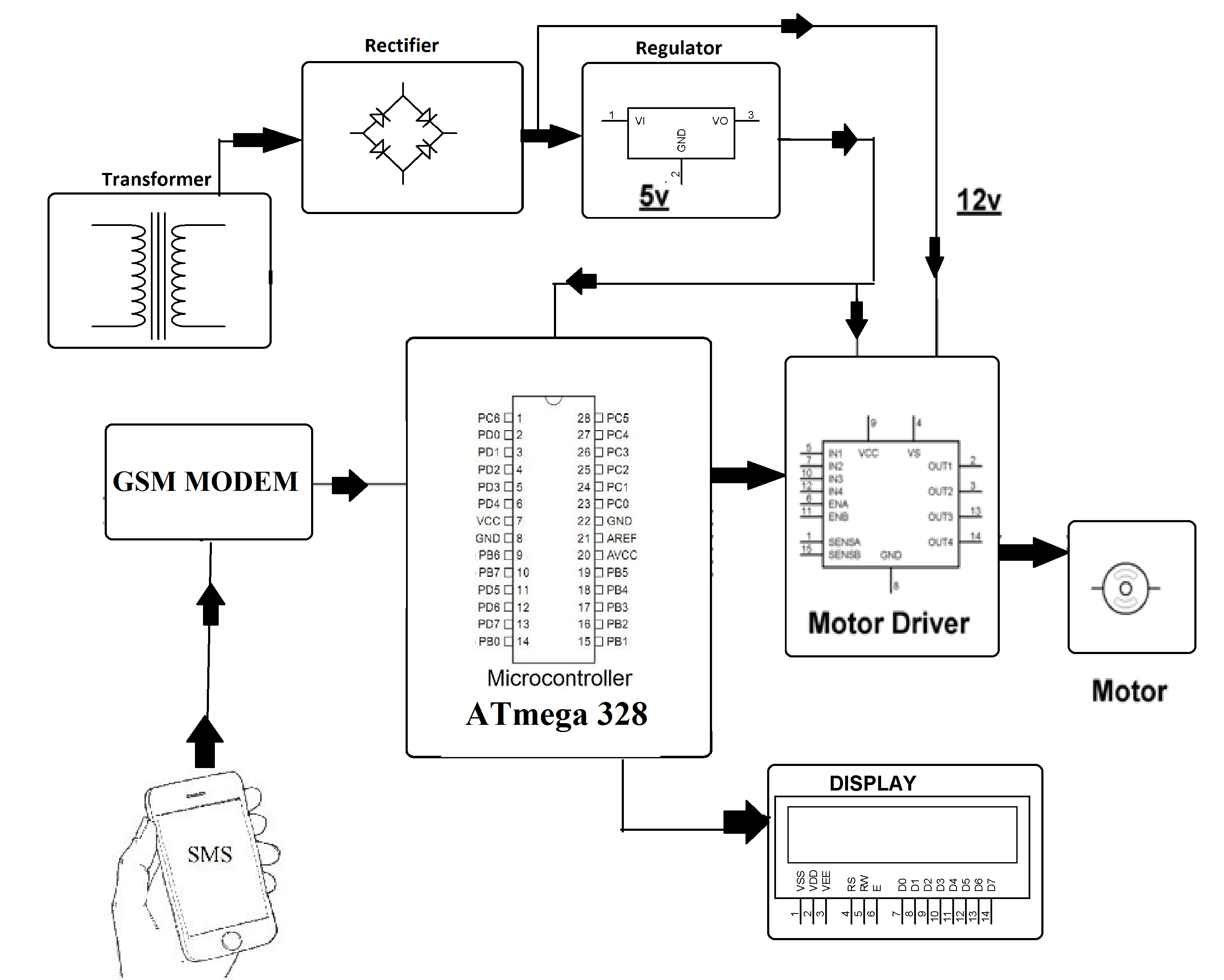
Dayton Dc Speed Control Wiring Diagram
44+ Dayton Dc Speed Control Wiring Diagram PNG. A first appearance at a circuit diagram could be confusing, yet if you can read a train map, you can read schematics. Bridgeport mill wiring diagram unique 2 5d to brushless dc motor.

Black wire connects negative power;
The circuit diagram of dc fan motor speed controller regulator circuit using 555. Project circuit schematic diagram is the one below. This circuit is based on 555 timer. U15 vcc_5vl 1 vcc 8.
Belum ada Komentar untuk "Dayton Dc Speed Control Wiring Diagram"
Posting Komentar